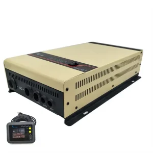
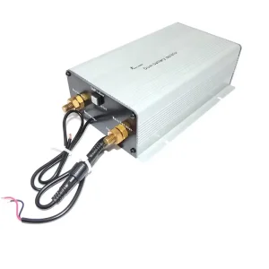
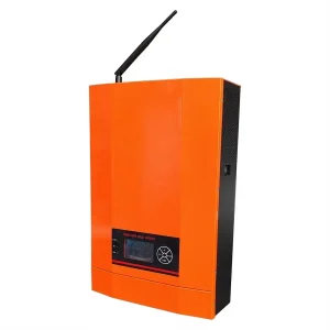
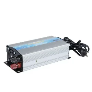
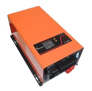
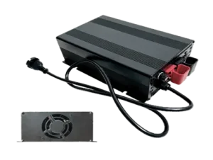
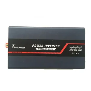
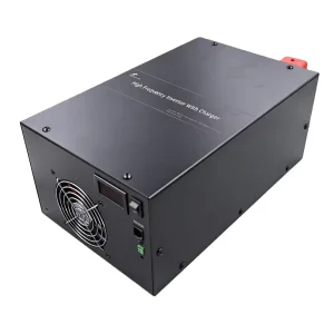
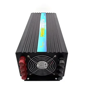
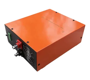
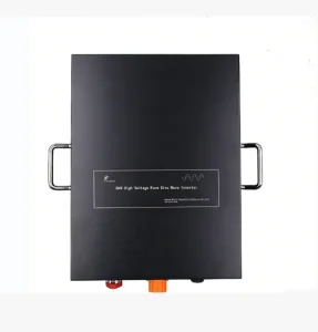
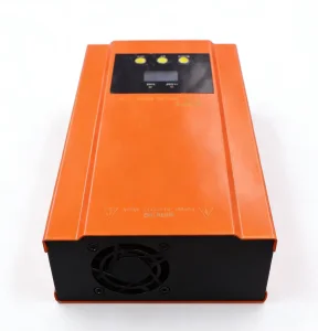
Explore high-performance, CE/CB/SAA-certified intelligent chargers and high-frequency inverters engineered for industrial vehicles, solar microgrids, marine energy systems, and telecommunication power back-ups.
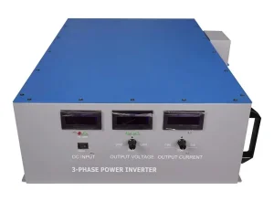
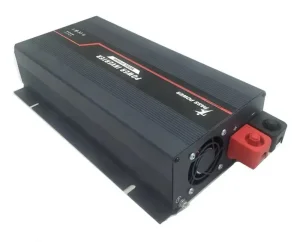
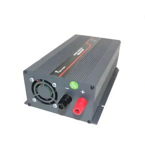
In the rapidly evolving global power electronics sector, 3-stage smart chargers have established themselves as the indisputable benchmark for industrial battery management. Legacy charging systems—historically dominated by unregulated constant-voltage or simple two-stage linear power supplies—are increasingly being phased out across North America, Europe, and the Asia-Pacific region. This migration is driven by strict energy efficiency directives (such as the EU's Ecodesign Directive and US DoE Level VI standards) and the imperative to maximize energy storage system (ESS) operational lifespans.
Electrochemically, lead-acid (AGM, GEL, Flooded) and lithium-iron-phosphate (LiFePO4) chemistries deteriorate rapidly under improper charge profiles. Overcharging causes electrolyte breakdown, plate sulfation, thermal runaway, and gas buildup, while undercharging leads to irreversible stratification and capacity loss. A microprocessor-controlled 3-stage charging algorithm resolves these failure modes by dividing the charging sequence into three distinct closed-loop stages:
During the initial phase, the smart charger delivers maximum rated current ($I_{max}$) into the battery bank while monitoring terminal voltage. This stage rapidly replenishes approximately 70% to 80% of total state-of-charge (SoC). The internal microprocessor regulates pulse-width modulation (PWM) switches to prevent current spikes, ensuring safe power transfer without exceeding the battery's maximum C-rate.
Once the battery terminal voltage reaches its predefined absorption threshold (typically 14.4V–14.8V for 12V lead-acid, or 14.6V for LiFePO4), the charger automatically transitions to constant voltage mode. The current gradually decays as internal cell resistance rises. This controlled "saturation" phase tops off the remaining 20% to 30% capacity without overheating the electrolyte or triggering BMS overvoltage disconnects.
Upon detecting that current acceptance has dropped below a set threshold (e.g., < 5% of rated capacity), the charger drops its output to a safe float voltage level (13.5V–13.8V). This offsets parasitic self-discharge and ambient loads without boiling off water in wet cells or causing dendrite growth in lithium cells, enabling indefinite 24/7 grid connection.
| Charger Topology Type | Energy Efficiency (%) | Battery Life Extension | Thermal Risk Index | Ideal Commercial Deployment |
|---|---|---|---|---|
| Legacy Linear / Unregulated Charger | 60% – 68% | Baseline (High Sulfation Risk) | High (Uncontrolled CV stage) | Legacy low-cost consumer tools |
| 2-Stage Switch-Mode Charger | 78% – 84% | +25% lifespan improvement | Moderate | Basic backup lighting, entry-level AGVs |
| 3-Stage Smart Charger (MCU / Microprocessor) | 92% – 96% | +100% to +150% lifespan extension | Negligible (Active thermal monitoring) | Marine, Off-grid Solar, RVs, Telecom, Mining |
| 4-Stage Intelligent Charger (with Recond/Desulfation) | 93% – 97% | +160% (Reclaims stratified lead-acid) | Negligible | Heavy industrial fleets, military logistics |
Top-tier 3-stage smart charger manufacturers employ state-of-the-art power conversion topologies to optimize footprint, minimize electromagnetic interference (EMI), and deliver high operational power density. At the core of modern smart chargers lies an integrated high-frequency Switch-Mode Power Supply (SMPS) topology operating at switching frequencies ranging from 65kHz to over 200kHz.
Industrial smart chargers incorporate continuous-conduction mode (CCM) APFC circuitry. This boosts input power factor to $\ge 0.99$ and reduces Total Harmonic Distortion (THD) to under 5%. APFC ensures compliance with EN 61000-3-2 standards, allowing high-power units (such as 12V 60A or 24V 30A chargers) to draw clean sine-wave current from unstable generator or grid power lines.
Thermal stress is the primary enemy of power MOSFETs and output rectifiers. Top manufacturers utilize extruded 6063-T5 aluminum alloy casings with integrated heat dissipation fins. Paired with intelligent temperature-controlled brushless DC cooling fans, heat is efficiently evacuated. Thermistors bonded to transformer windings continuously report thermal data to the MCU, initiating automatic current derating if ambient temperatures surpass $60^\circ\text{C}$.
Modern B2B procurement demands versatility. Leading smart chargers feature DIP switches or LCD interfaces that reconfigure the MCU firmware's voltage setpoints. A single unit can seamlessly switch between flooded lead-acid profiles (requiring equalize charges at 15.5V), sealed AGM profiles (fixed absorption at 14.4V), and LiFePO4 profiles (requiring precise 14.6V CV limit with 0V wake-up pulses to reset tripped BMS protection boards).
Global distributors, OEMs, and brand owners sourcing smart chargers leverage the unrivaled production efficiency and supply chain density concentrated in Chinese manufacturing hubs—particularly within Jiangsu Province (such as Suzhou) and the Pearl River Delta. China’s leadership in smart charger and power converter manufacturing is anchored on four structural pillars:
Within a 50-kilometer radius of major manufacturing parks, factories have direct access to copper magnet wire drawing, high-frequency magnetic core pressing (ferrite cores), high-voltage electrolytic capacitor factories, and semiconductor packaging plants. This ultra-dense supply cluster reduces component lead times from weeks to hours, enabling agile response to bulk custom orders.
State-of-the-art Chinese smart charger factories operate fully automated Surface Mount Technology (SMT) lines equipped with 3D Automated Optical Inspection (AOI), In-Circuit Testing (ICT), and automated conformal coating application. Every single unit undergoes a 100% full-load aging burn-in test inside controlled elevated-temperature chambers ($45^\circ\text{C}$ for 4 to 8 hours) prior to final packaging.
Unlike Western manufacturers constrained by rigid off-the-shelf product lines, Chinese factories excel at bespoke customization. Engineering teams can modify DC cable length, terminal connectors (Anderson plugs, ring terminals, alligator clips), CAN-Bus communication protocols (J1939 or RV-C), localized AC plug configurations, custom aluminum housing anodization, and branded LCD boot screens at competitive minimum order quantities (MOQs).
The versatile nature of 3-stage smart chargers allows them to serve critical power infrastructure across diverse commercial, marine, and industrial operational environments:
Marine environments expose electronics to humidity, salt spray, and vibration. Marine-grade 3-stage chargers feature conformal-coated PCBs, stainless steel hardware, and IP65/IP67 rated enclosures. They manage dual or triple battery banks (starting batteries and house banks) via isolated outputs, ensuring house deep-cycle batteries recharge without compromising engine starting capabilities.
Recreational vehicle builders integrate compact aluminum 12V 30A/60A smart chargers into power distribution centers. Paired with shore power or onboard generators, these chargers quickly replenish LiFePO4 house batteries during short campsite stops. Integrated temperature probes adjust charge voltage in real time to adapt to freezing outdoor temperatures or scorching summer deserts.
Ambulances, fire engines, and utility service trucks rely on 3-stage smart chargers to power critical onboard medical equipment, radios, and power tools while parked in station bays. Auto-eject AC connectors paired with float charging ensure vehicle batteries remain at 100% SoC around the clock, guaranteeing instant engine cranking during emergency dispatches.
In off-grid telecommunications, hybrid solar-diesel base stations utilize high-efficiency 48V 3-stage chargers. When solar irradiance drops, backup diesel generators activate; the smart charger rapidly absorbs power at high current to minimize generator runtime and fuel consumption, switching smoothly to float mode as the battery reaches saturation.
Procurement officers and sourcing managers evaluating smart charger factories must conduct multi-dimensional due diligence to mitigate operational, legal, and quality risks. Below is the framework adopted by Fortune 500 equipment buyers:
The smart charger industry is undergoing a major technological transformation, accelerated by wide-bandgap (WBG) semiconductors, IoT connectivity, and vehicle-to-everything (V2X) energy integration:
Next-generation 3-stage chargers are replacing traditional Silicon MOSFETs with GaN and SiC power devices. Switching frequencies exceeding 500kHz dramatically reduce the physical size of planar transformers and inductors, enabling up to 40% reduction in charger casing volume while pushing thermal efficiency past 97%.
Smart chargers are transitioning from isolated devices to fully connected IoT nodes. Integration of CAN-Bus, RS485 Modbus, and Bluetooth/Wi-Fi modules allows real-time telemetry transmission to fleet management dashboards. Predictive maintenance algorithms analyze charging curve trends to alert operators of degradation before a battery cell fails.
The boundary between battery chargers and grid-tied inverters is blurring. Future 3-stage chargers will feature bi-directional topologies, allowing stored energy in commercial vehicle fleets or energy storage systems to feed power back into facility microgrids during peak demand pricing periods.
Discover Maili Electric's comprehensive energy ecosystem, including high-efficiency pure sine wave inverters, MPPT solar controllers, and intelligent dual battery isolators.