
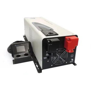


Explore our factory-direct CE-certified high-frequency chargers, low-frequency inverter chargers, and hybrid solar power management systems.
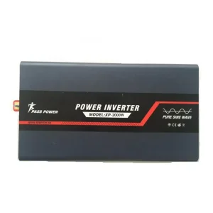
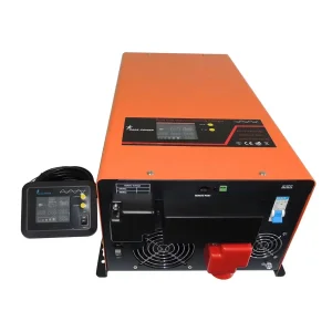
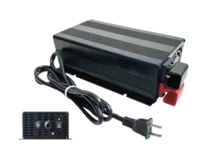
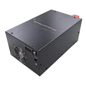
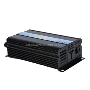
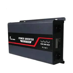
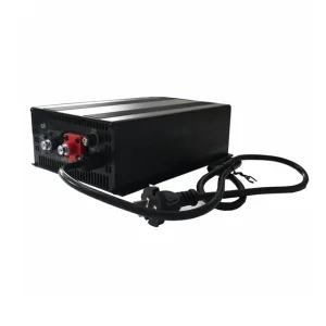
A Comprehensive Industry Guide for Commercial Procurement Directors, Electrical Systems Integrators, and Off-Grid Equipment OEMs.
Modern electrical energy storage systems demand highly precise charging topologies to ensure operational reliability, prevent premature capacity degradation, and eliminate thermal runaway risks. Legacy single-stage or constant-voltage linear chargers subject batteries to severe overcharging stress, electrolyte gassing, plate sulfation, and internal cell degradation. As a premier China manufacturer of power electronics, our R&D engineering division specializes in designing CE-certified 3-stage intelligent battery chargers that utilize high-frequency Pulse-Width Modulation (PWM) and resonant LLC conversion architectures managed by embedded 32-bit microcontrollers (MCUs).
By actively analyzing the state-of-charge (SoC), internal resistance variations, and ambient operating temperatures in real-time, 3-stage intelligent chargers deliver dynamically adjusted charging profiles. Whether integrated into marine vessels, commercial recreational vehicles (RVs), emergency services fleets, stationary solar energy storage systems (ESS), or industrial telecommunications infrastructure, our chargers deliver optimal energy transfer while adhering strictly to European Union Low Voltage Directive (LVD 2014/35/EU) and Electromagnetic Compatibility (EMC 2014/30/EU) compliance mandates.
Understanding Bulk, Absorption, and Float phases in advanced lead-acid and lithium battery care.
During the initial charging phase, the intelligent charger operates as a regulated Constant Current (CC) source, delivering maximum rated output current (e.g., 30A, 40A, or 80A) into the depleted battery bank. This phase rapidly replenishes approximately 80% of the battery's state-of-charge (SoC).
Advanced microcontroller algorithms continuously monitor terminal voltage rise. If a severely discharged battery (<10V for a 12V bank) is detected, the MCU initiates a soft-start pre-charge routine to prevent thermal shock to the internal battery plates before ramping up to full bulk current.
Once the battery terminal voltage reaches the pre-programmed absorption threshold (typically 14.4V–14.8V for lead-acid, or 14.2V–14.6V for LiFePO4), the charger automatically transitions to a Constant Voltage (CV) mode.
As internal resistance increases near full capacity, current acceptance naturally tapers down. The intelligent firmware accurately tracks current decay (dI/dt). Once current drops below a factory-set threshold (typically 5%–10% of maximum current rating), the charger terminates the absorption phase, preventing electrolyte boiling and grid corrosion.
In the final phase, the voltage is reduced to a safe, continuous float level (typically 13.5V–13.8V for SLA/GEL batteries). This float voltage offsets self-discharge losses without causing positive plate degradation or water loss.
For standby backup power and seasonal storage, our smart chargers implement an auto-refresh pulse trickle routine every 7 to 14 days to prevent acid stratification in flooded cells and maintain passive cell balancing in Lithium Iron Phosphate (LiFePO4) battery packs equipped with a BMS.
| Battery Chemistry | Bulk (CC) Voltage (12V Base) | Absorption (CV) Voltage | Float Maintenance Voltage | Temperature Coefficient | Desulfation / Equalization |
|---|---|---|---|---|---|
| AGM (Absorbed Glass Mat) | 14.4V - 14.6V | 14.4V (Fixed Time / dI/dt Cutoff) | 13.6V - 13.8V | -3mV / °C / cell | Not Recommended |
| GEL Deep Cycle | 14.0V - 14.2V | 14.2V (Low Voltage Limit) | 13.5V - 13.7V | -4mV / °C / cell | Disabled (Strict Voltage Cap) |
| Flooded Lead-Acid (WET) | 14.6V - 14.8V | 14.8V (High Current Accept) | 13.5V - 13.6V | -3mV / °C / cell | Automated High-Voltage Pulse (15.5V) |
| LiFePO4 (Lithium) | 14.4V - 14.6V | 14.4V (Fast Termination) | 13.5V - 13.6V (Optional Standby) | 0 (NTC Monitored Cutoff) | Disabled (BMS Balancing Active) |
How Suzhou and Yangtze River Delta Electronics Ecosystems Deliver Unmatched Quality, Cost Efficiency, and Customization Velocity.
Our manufacturing plant in Suzhou operates within China's primary power electronics cluster. This location grants direct access to premium Silicon Carbide (SiC) and Gallium Nitride (GaN) semiconductor vendors, custom magnetic core suppliers (EPCOS/TDK ferrite transformers), and high-grade solid aluminum capacitor makers. This integrated supply chain reduces component lead times and mitigates international logistics risks.
Every intelligent battery charger undergoing production is subjected to stringent automated quality control processes: Surface Mount Technology (SMT) Automated Optical Inspection (AOI), 100% full-load thermal burn-in testing for 4 hours at 50°C ambient, and high-voltage dielectric withstand isolation testing (HI-POT test up to 3000V AC). CE certification ensures full compliance with conducted and radiated emissions standards.
We provide extensive white-label and bespoke ODM engineering capabilities for global distributors. This includes customized DC/AC voltage outputs (12V, 24V, 36V, 48V, 72V, 96V), proprietary algorithm flash programming for emerging lithium chemistries, custom LCD display branding, CAN bus / Modbus communication protocol integration, and ruggedized IP65/IP67 enclosure designs.
How Power Electronics Manufacturers Are Adapting to Smart Grids, IoT Communication, and Wide-Bandgap Semiconductors.
The global battery charging equipment market is undergoing a structural transition driven by electrification across mobile and stationary power sectors. Key technical vectors reshaping product development include:
Tailored Energy Management Systems for Mission-Critical Deployment Environments Worldwide.
In mobile RV electrical systems, our 3-stage smart chargers integrate seamlessly with dual battery isolators and alternator charging setups. They accept noisy generator AC input or fluctuating shore power (90V–264V AC wide input range) and supply smooth DC power to deep-cycle house battery banks while running 12V DC onboard cabin lighting and refrigeration systems.
Saltwater environments demand heavy-duty corrosion protection. Our marine-grade smart chargers feature conformal-coated internal circuit boards (PCBs), anodized aluminum alloy housings, and IP65 drip-proof protection. Multi-bank output chargers allow isolated charging of engine starter batteries and deep-cycle trolling/house banks simultaneously.
In remote cellular tower base stations and off-grid solar-diesel hybrid setups, 3-stage intelligent battery chargers serve as primary rectifiers. Operating with extremely low output ripple (<100mV peak-to-peak), they prevent high-frequency interference on telecom transmission bands while maintaining standby power banks in full float condition.
Ambulances, fire rescue vehicles, and police mobile command units rely on continuous auxiliary power. Our chargers feature auto-detect shore-power ejector handshaking and reverse polarity safety interlocks to keep emergency medical power equipment and radio systems continuously primed without risking operator error.
Key Engineering Parameters to Evaluate Before Signing OEM/ODM Battery Charger Supply Contracts.
When sourcing industrial-grade 3-stage intelligent battery chargers in bulk, professional purchasing managers and engineering directors should systematically evaluate the following performance criteria:
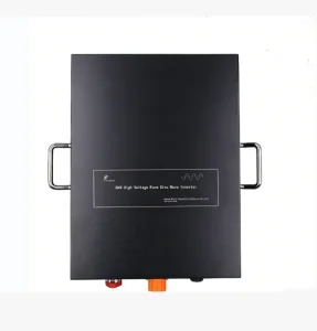
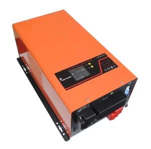
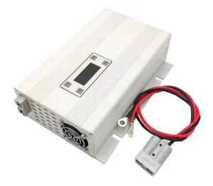
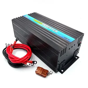
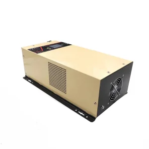
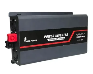
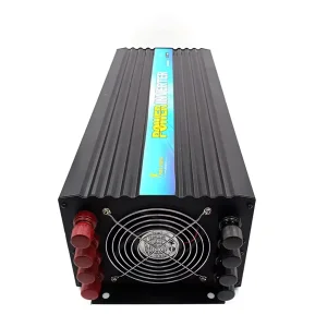
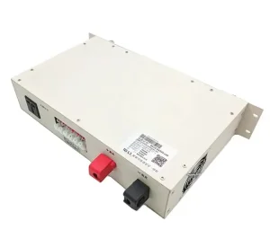
Complete your power architecture with high-voltage industrial inverters, pure sine wave converters, and custom vehicle power systems.
Answers to key engineering, certification, and purchasing inquiries regarding 3-stage intelligent chargers.
Traditional single-stage chargers supply a fixed voltage or un-regulated current, which leads to severe overcharging once the battery reaches ~80% capacity. This causes electrolyte boiling, gas venting in flooded batteries, thermal degradation, and plate sulfation. A 3-stage intelligent charger uses an embedded microprocessor to dynamically shift between Bulk (Constant Current), Absorption (Constant Voltage), and Float (Maintenance Voltage). This process optimizes energy transfer speed, caps peak charging voltage to safe levels, and extends overall battery cycle life by up to 300%.
Our CE certification consists of full compliance testing under two primary European Directives:
Yes. While lead-acid batteries require extended float maintenance phases, LiFePO4 chemistry requires a precise 2-stage or modified 3-stage profile (Constant Current to Constant Voltage termination with optional standby refresh). Our smart chargers can be pre-programmed at our factory with custom LiFePO4 profiles, including 0°C low-temperature charging cutoff protection to prevent lithium plating on the anode.
Chemical reaction rates inside batteries accelerate in hot environments and slow down in cold weather. An external Negative Temperature Coefficient (NTC) thermistor probe connected to the battery terminal relays real-time thermal data back to the charger's microcontroller. The charger dynamically adjusts voltage by approximately -3mV/°C/cell for lead-acid batteries—raising voltage in cold weather to achieve full charge and lowering voltage in hot environments to prevent thermal runaway.
We provide full white-label manufacturing services, including:
Our intelligent chargers feature multi-layer safety protections: internal reverse-polarity solid-state MOSFET switches or heavy-duty relay isolators prevent sparks or current flow if positive and negative leads are incorrectly connected. Additional protective circuits include hardware Output Short Circuit Protection (auto-recovery), Over Voltage Protection (OVP), Over Current Protection (OCP), and internal Over Temperature Protection (OTP) that throttles output current or initiates a safe shutdown if internal heat sink temperatures exceed 85°C.